
Image Source: i.ytimg.com
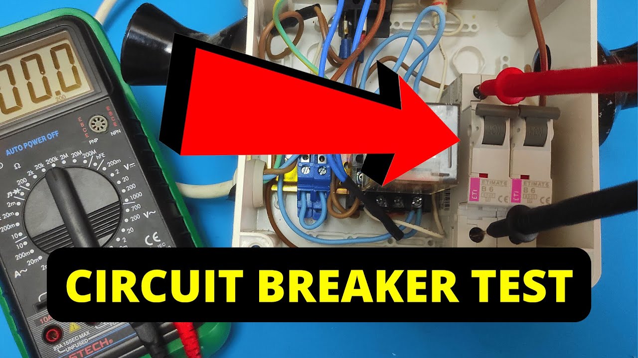
How To Test A Circuit Breaker With A Multimeter
Can you test a circuit breaker with a multimeter? Yes, you absolutely can! A multimeter is a powerful tool that can help you determine if a circuit breaker is working correctly or if it has failed. This guide will walk you through the essential steps to test a circuit breaker using a multimeter, ensuring your electrical systems are safe and functional. Testing a circuit breaker is a crucial part of troubleshooting circuits and can prevent further electrical issues.
Why Test a Circuit Breaker?
Circuit breakers are the silent guardians of your home’s electrical system. They are designed to protect your wiring and appliances from damage caused by overcurrents, such as those from short circuits or overloads. When a circuit breaker “trips,” it means it has done its job, safely interrupting the flow of electricity. However, sometimes a circuit breaker might appear to be working, but it has actually failed internally, no longer providing adequate protection. This can lead to overloaded circuits, damaged equipment, and even fire hazards. Regularly testing your circuit breakers can give you peace of mind and help prevent these dangerous situations. It’s a key aspect of maintaining electrical safety.
What is a Multimeter?
A multimeter is a versatile electronic measuring instrument that combines several measurement functions in one unit. The most common functions are measuring voltage, current, and resistance. For testing circuit breakers, we’ll primarily focus on its voltage test and continuity test capabilities. Many multimeters also offer a resistance measurement function, which is directly related to checking continuity. Some advanced multimeters can even perform basic fuse testing in a similar manner. When you use a multimeter, it’s important to select the correct multimeter settings for the task at hand.
Preparing for the Test: Safety First!
Before you even touch a multimeter or a circuit breaker, electrical safety is paramount. Working with electricity can be dangerous, even at lower voltages. Always follow these safety precautions:
- Turn off the power: This is the MOST important step. Go to your main electrical panel and switch off the breaker controlling the circuit you intend to test. If you are unsure which breaker controls which circuit, turn off the main breaker for the entire house.
- Verify power is off: Use your multimeter to confirm that there is no power to the circuit you are testing. You will perform a voltage test on the outlets or fixtures connected to the breaker you are about to examine.
- Wear appropriate safety gear: Consider wearing safety glasses and insulated gloves, especially if you are working in a damp environment or are unfamiliar with electrical work.
- Use a properly rated multimeter: Ensure your multimeter is rated for the voltages you might encounter. Most household circuits operate at 120V or 240V, so a multimeter with a CAT III or CAT IV rating is recommended.
- Inspect your equipment: Before use, check your multimeter and its probes for any signs of damage, such as frayed wires or cracked casings.
Tools You’ll Need
- Digital Multimeter: A reliable digital multimeter is essential.
- Screwdriver: You might need a Phillips or flat-head screwdriver to remove the breaker panel cover.
- Safety Glasses: To protect your eyes.
- Insulated Gloves (Optional but Recommended): For added protection.
Testing a Circuit Breaker: Step-by-Step
We’ll break down the process into several tests, each targeting a different aspect of the circuit breaker function.
Method 1: The Voltage Test (The Most Common Method)
This method is excellent for checking if the breaker is allowing power to pass through when it’s in the “ON” position and if it’s correctly interrupting power when in the “OFF” position.
Step 1: Set Up Your Multimeter for Voltage Measurement
- Select AC Voltage: Turn the dial on your multimeter to the AC voltage setting (V~ or VAC). Choose a range that is higher than the expected voltage (e.g., 200V or 600V for typical household circuits).
- Insert Probes: Place the red probe into the “V” or “VΩmA” jack and the black probe into the “COM” (common) jack.
Step 2: Check Voltage at the Breaker Terminals
This involves accessing the breaker terminals, which requires removing the breaker panel cover. If you are not comfortable with this, it’s best to call a qualified electrician.
Safety Reminder: Ensure the main breaker is OFF before removing the panel cover.
- Locate the Breaker: Identify the circuit breaker you want to test in your electrical panel.
- Remove the Panel Cover: Carefully unscrew and remove the outer cover of your electrical panel to expose the breakers.
- Identify Terminals: Each circuit breaker has two main terminals where wires connect.
- Line Terminal: This terminal receives power from the main bus bar in the panel.
- Load Terminal: This terminal sends power out to the circuit.
- Test with Breaker ON:
- Turn the circuit breaker to the “ON” position.
- Carefully touch the red probe to the line terminal of the breaker.
- Touch the black probe to the neutral bus bar (a common metal bar where white wires are connected) or to the ground bus bar (a metal bar where green or bare copper wires are connected).
- Your multimeter should display the expected voltage (e.g., around 120V or 240V). If you get zero voltage, there’s a problem with the power supply to the breaker itself.
- Now, with the red probe still on the line terminal, touch the black probe to the load terminal of the breaker.
- Again, you should see the same voltage reading as before. If you get zero or a significantly lower voltage, the breaker is not passing power, indicating a potential internal fault.
Step 3: Test with Breaker OFF
- Turn the Breaker OFF: Switch the circuit breaker to the “OFF” position.
- Repeat Voltage Test:
- With the red probe on the line terminal and the black probe on the load terminal, your multimeter should read zero volts (or a very low, negligible voltage). If you still get a voltage reading, the breaker is not interrupting the flow of power, which is a serious fault.
Interpreting Voltage Test Results:
- Breaker ON:
- Voltage present at the line terminal, absent at the load terminal: Breaker has failed to pass power.
- Voltage present at both terminals: Breaker is passing power.
- Breaker OFF:
- Zero voltage at both terminals: Breaker is interrupting power.
- Voltage present at the load terminal: Breaker has failed to interrupt power.
Method 2: The Continuity Test (Checking for a Complete Path)
A continuity test checks if there is an unbroken path for electricity to flow between two points. For a circuit breaker, this means checking if the internal contacts are making a good connection when the breaker is “ON” and if they are effectively breaking the connection when “OFF.” This is similar to fuse testing where you confirm a continuous path.
Step 1: Set Up Your Multimeter for Continuity
- Select Continuity Mode: Turn the dial on your multimeter to the continuity setting. This is often represented by a symbol that looks like a sound wave or a diode symbol. When continuity is detected, most multimeters will emit an audible beep.
- Insert Probes: Ensure the probes are in the correct jacks (red to “VΩmA” or “V” and black to “COM”).
Step 2: Perform the Continuity Test
Safety Reminder: It is CRITICAL that the power to the circuit breaker is completely OFF for this test. Turn off the breaker at the panel, and ideally, turn off the main breaker as well.
- Remove the Breaker from the Panel (Recommended): For the most accurate continuity test, it’s best to physically remove the circuit breaker from the electrical panel. This ensures you’re not measuring through other components in the panel. Most breakers simply pull straight out after being disengaged from the bus bar.
- Identify Terminals: Locate the two screw terminals on the breaker where the wires would normally connect.
- Test with Breaker ON:
- Place the probes of your multimeter firmly onto the two terminals of the circuit breaker.
- Turn the circuit breaker to the “ON” position.
- Your multimeter should beep, indicating continuity (a complete path). If it doesn’t beep, the breaker’s internal contacts are not making a good connection.
- Test with Breaker OFF:
- Turn the circuit breaker to the “OFF” position.
- Place the probes on the same two terminals.
- Your multimeter should NOT beep. If it beeps, the breaker is not properly breaking the circuit.
Interpreting Continuity Test Results:
- Breaker ON:
- Beeps: Good connection.
- No beep: Bad connection (breaker has failed).
- Breaker OFF:
- No beep: Good disconnection.
- Beeps: Bad disconnection (breaker has failed).
Method 3: Resistance Measurement (Quantifying the Connection)
This method is essentially a more precise version of the continuity test, using the ohm meter function of your multimeter. It provides a numerical reading of the resistance in the circuit breaker’s path.
Step 1: Set Up Your Multimeter for Resistance Measurement
- Select Resistance Mode: Turn the dial on your multimeter to the resistance setting (Ω). Choose a low range (e.g., 200 ohms).
- Insert Probes: Ensure the probes are in the correct jacks (red to “VΩmA” or “V” and black to “COM”).
Step 2: Perform the Resistance Test
Safety Reminder: Power MUST be OFF for this test.
- Remove the Breaker from the Panel (Recommended): As with the continuity test, removing the breaker provides the most accurate readings.
- Identify Terminals: Locate the two screw terminals on the breaker.
- Test with Breaker ON:
- Place the probes of your multimeter firmly onto the two terminals.
- Turn the circuit breaker to the “ON” position.
- Your multimeter should display a very low resistance reading, ideally close to 0 ohms. A reading of a few ohms or more might indicate dirty or corroded internal contacts, suggesting a potential issue.
- Test with Breaker OFF:
- Turn the circuit breaker to the “OFF” position.
- Place the probes on the same two terminals.
- Your multimeter should display an “OL” (Over Limit) or a very high resistance reading, indicating an open circuit. If you get a low resistance reading, the breaker is not opening the circuit.
Interpreting Resistance Measurement Results:
- Breaker ON:
- Very low resistance (close to 0 Ω): Good connection.
- High resistance (e.g., several ohms or more): Potentially faulty contacts.
- Breaker OFF:
- “OL” or very high resistance: Good disconnection.
- Low resistance: Faulty breaker, not opening the circuit.
What if the Breaker Fails the Test?
If your tests indicate a faulty circuit breaker, it’s crucial to replace it immediately. A malfunctioning breaker compromises your home’s electrical safety.
- Turn off the Main Breaker: Before attempting any replacement, ensure the main power to your home is shut off.
- Remove the Faulty Breaker: If you haven’t already, carefully remove the old breaker from the panel.
- Install the New Breaker: Ensure the new breaker is the same amperage rating and type as the old one. Connect the wire from the circuit to the new breaker’s load terminal and clip the breaker into the panel.
- Restore Power: Turn the main breaker back on, then the individual breaker you replaced.
- Test Again: Use your multimeter to perform a quick voltage test to confirm the new breaker is functioning correctly.
Common Issues and Troubleshooting
- No Voltage at the Line Terminal: If you get no voltage at the line terminal even with the main breaker on, the problem lies upstream from the breaker, possibly with the utility feed or the main breaker itself.
- Breaker Trips Immediately: If a breaker trips as soon as you turn it on, this indicates a direct short circuit on the protected line. Do not reset it repeatedly; investigate the appliances or wiring connected to that circuit.
- Intermittent Tripping: This can be caused by an overloaded circuit or a faulty breaker that is sensitive to minor fluctuations.
- Corroded Terminals: Over time, breaker terminals can corrode, leading to poor connections and increased resistance. Cleaning these can sometimes resolve minor issues, but replacement is often necessary for safety.
Frequently Asked Questions (FAQ)
Q1: Can I test a circuit breaker without a multimeter?
While you can observe if a breaker has tripped, a multimeter is essential for definitively testing its circuit breaker function and ensuring it’s working correctly when it appears to be “ON.” Without it, you can’t accurately measure voltage or continuity.
Q2: What do the different CAT ratings on a multimeter mean?
CAT (Category) ratings indicate the level of transient voltage protection a meter offers. CAT III is for distribution level systems (like branch circuits in your home), and CAT IV is for source level (like the utility meter). For home electrical work, a CAT III or CAT IV meter is recommended for safety.
Q3: How often should I test my circuit breakers?
While there’s no strict schedule, it’s good practice to perform visual checks periodically and a multimeter test if you suspect an issue, especially if a breaker has tripped unusually or if you’re performing other electrical work.
Q4: Can I test a GFCI or AFCI breaker differently?
GFCI (Ground Fault Circuit Interrupter) and AFCI (Arc Fault Circuit Interrupter) breakers have built-in test buttons for their specific functions. However, you can still perform the basic voltage and continuity tests described above to check their general condition.
Q5: What is the acceptable resistance for a good circuit breaker?
Ideally, a good circuit breaker should have a resistance close to 0 ohms when ON and an infinite or very high resistance when OFF. Readings above a few ohms when ON might suggest a problem.
By following these detailed steps, you can confidently use your multimeter to test your circuit breakers, contributing to a safer and more reliable electrical system in your home. Remember, if you are ever unsure or uncomfortable with any part of this process, it is always best to consult a qualified electrician.